

Building an nRF52840 Web Server: A Minimal UARTE Logger for Debugging
Read the complete article on my website →
Preface
The first and most important thing that I built for the project is a logger to send logs over UARTE. This is quite important, as logging gets you out of tough situations. The nRF52840 DK exposes the nRF52840’s UARTE peripheral through its onboard J-Link debugger as a virtual COM (VCOM) port, which makes it convenient for sending logs to a PC over USB. This will change on the final custom PCB, where there will be no onboard debugger. In that case, I will likely use a USB-to-serial bridge to convert the board’s UART signals into a USB serial port that can be opened from a PC.
I already explored TX-only UARTE logging in the bare-metal article, including basic transmission and viewing the output over the J-Link VCOM port. This logger builds on that work for FreeRTOS.
GitHub Repo: https://github.com/codetit4n/nrf52840-webserver
Design Goals
Before implementing it, here are the goals I had in mind:
The logger should be TX-only, i.e., it should only send messages over UART.
Logging should work from multiple FreeRTOS tasks.
Only the logger task should own the UARTE peripheral.
The logger task should have the lowest priority so it does not interfere with higher-priority tasks such as networking.
Log messages should be buffered using a ring buffer, allowing producer tasks to keep adding logs while the logger task processes and transmits them.
Architecture
Logger data flow

UARTE/VCOM Physical Path

NOTE: There are two UARTE instances on the nRF52840. This project uses
UARTE0.
The architecture is split into two paths. On the software side, FreeRTOS tasks, such as networking and storage, enqueue log messages into a ring buffer, which are then processed by the logger task and transmitted through UARTE0. On the hardware side, the UARTE TX signal is routed through the onboard J-Link debugger, exposed as a VCOM port, and sent to the PC over USB.
UARTE Driver
The driver code is the layer between the logger API and the actual hardware. So, we need to do the direct register tinkering in this layer.
Relevant Source Code
Board Config Header - include/board.h
Driver Header - include/drivers/uarte.h
Driver Source - src/drivers/uarte.c
Registers
Registers for configuration, tasks, and events needed to operate the peripheral are declared in board.h:
#include "nrf52840.h"

#define UARTE NRF_UARTE0
#define UARTE_ENABLE_REG (UARTE->ENABLE)
#define UARTE_CONFIG_REG (UARTE->CONFIG)
#define UARTE_BAUDRATE_REG (UARTE->BAUDRATE)
#define UARTE_TXD_PTR_REG (UARTE->TXD.PTR)
#define UARTE_TXD_MAXCNT_REG (UARTE->TXD.MAXCNT)
#define UARTE_TASKS_STARTTX_REG (UARTE->TASKS_STARTTX)
#define UARTE_TASKS_STOPTX_REG (UARTE->TASKS_STOPTX)
#define UARTE_EVENTS_ENDTX_REG (UARTE->EVENTS_ENDTX)
#define UARTE_EVENTS_TXSTOPPED_REG (UARTE->EVENTS_TXSTOPPED)

#define UARTE_PSEL_TXD_REG (UARTE->PSEL.TXD)
#define UARTE_PSEL_RXD_REG (UARTE->PSEL.RXD)

#define TX_PIN 6 // P0.06: UARTE0 TXD -> DK J-Link VCOM RX
#define RX_PIN 8 // P0.08: UARTE0 RXD <- DK J-Link VCOM TX (unused here)
NOTE: The register definitions are included from nrf52840.h. That is the only use of the included
nrf52840.hfile in the source code.
In UARTE, the DMA moves the bytes while the CPU mostly stays out of it. So, all we need to do is control these registers to operate the UARTE peripheral. Since we are using EasyDMA here, the CPU does not have to manually move every byte.
Initialization, Configuration & Recovery
Initialization and Configuration
The uarte_init() function is used to initialize the UARTE0 peripheral. This function is called when the device is turned on and brings up the hardware.
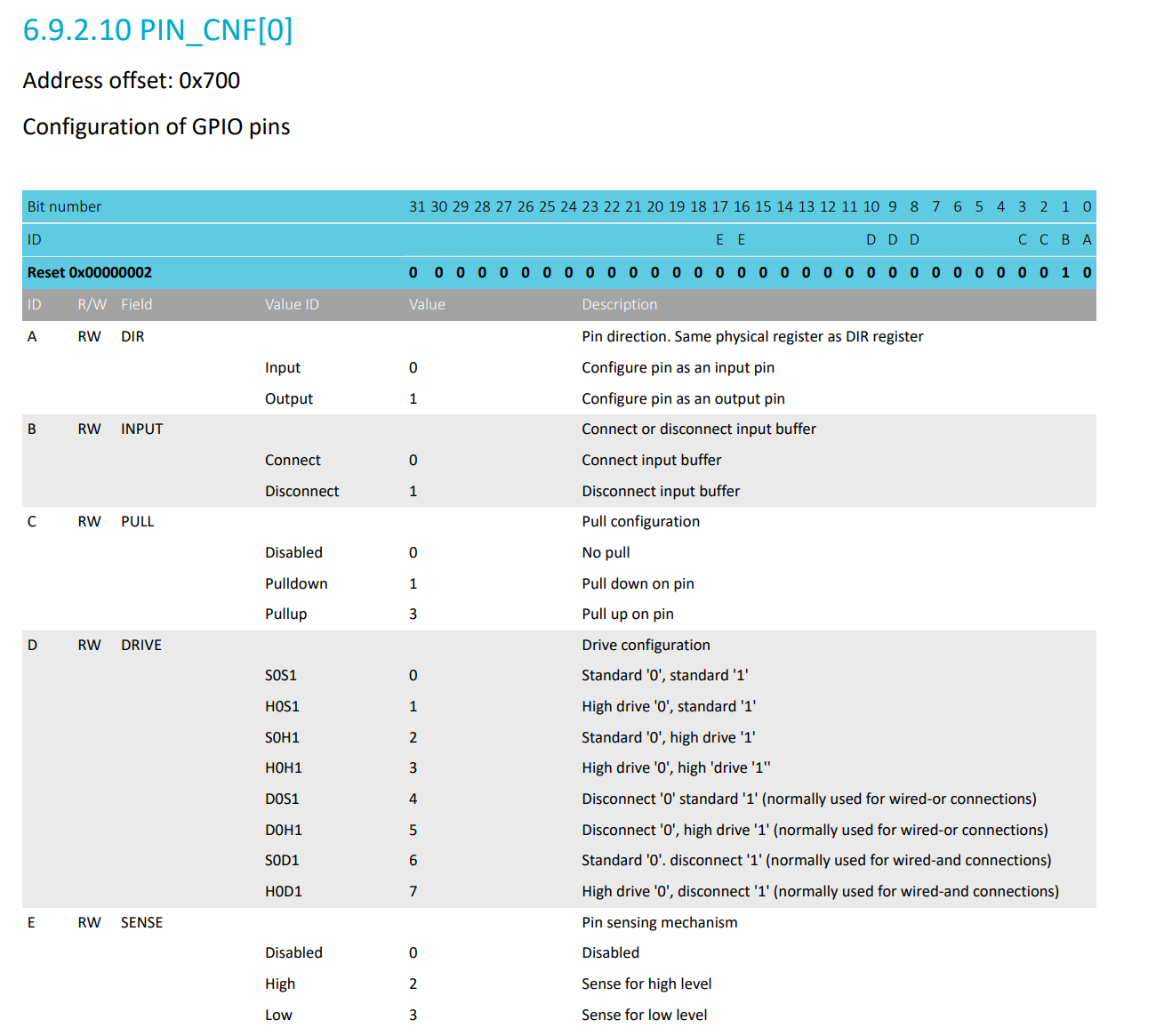
GPIO Configuration for the TX Pin:
GPIO_CNF(TX_PIN) = (1 << 0) | // DIR = Output
                   (1 << 1) | // INPUT disconnect (input buffer not needed for TX)
                   (0 << 2) | // PULL = none (field)
                   (0 << 8) | // DRIVE = standard (field)
                   (0 << 16); // SENSE = disabled

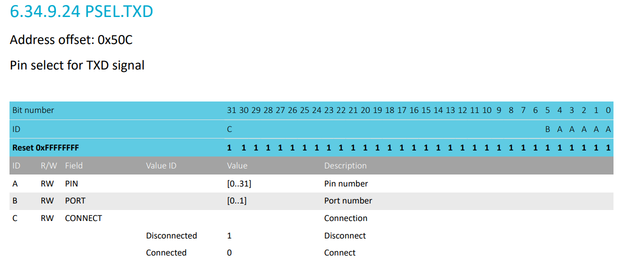
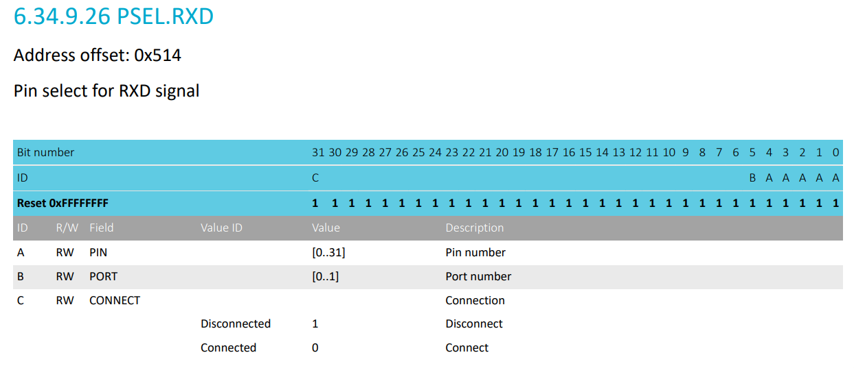
// PSEL format: PIN[4:0] | PORT(bit5) | CONNECT(bit31: 0=connected, 1=disconnected)
UARTE_PSEL_TXD_REG = (TX_PIN << 0) | (0 << 5) | (0 << 31);

UARTE_PSEL_RXD_REG = (1 << 31); // RX disconnected (TX-only)
NOTE: RX_PIN configuration is not needed as this is TX-only.
Datasheet Reference
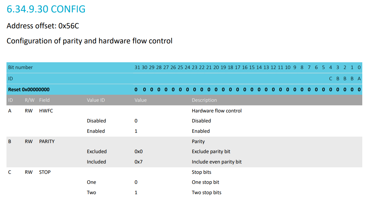
Configure the UARTE peripheral: set baud rate, clear events, etc.
UARTE_CONFIG_REG = (0 << 0) |   // HWFC disabled
                   (0x0 << 1) | // PARITY excluded
                   (0 << 4);    // 1 stop bit

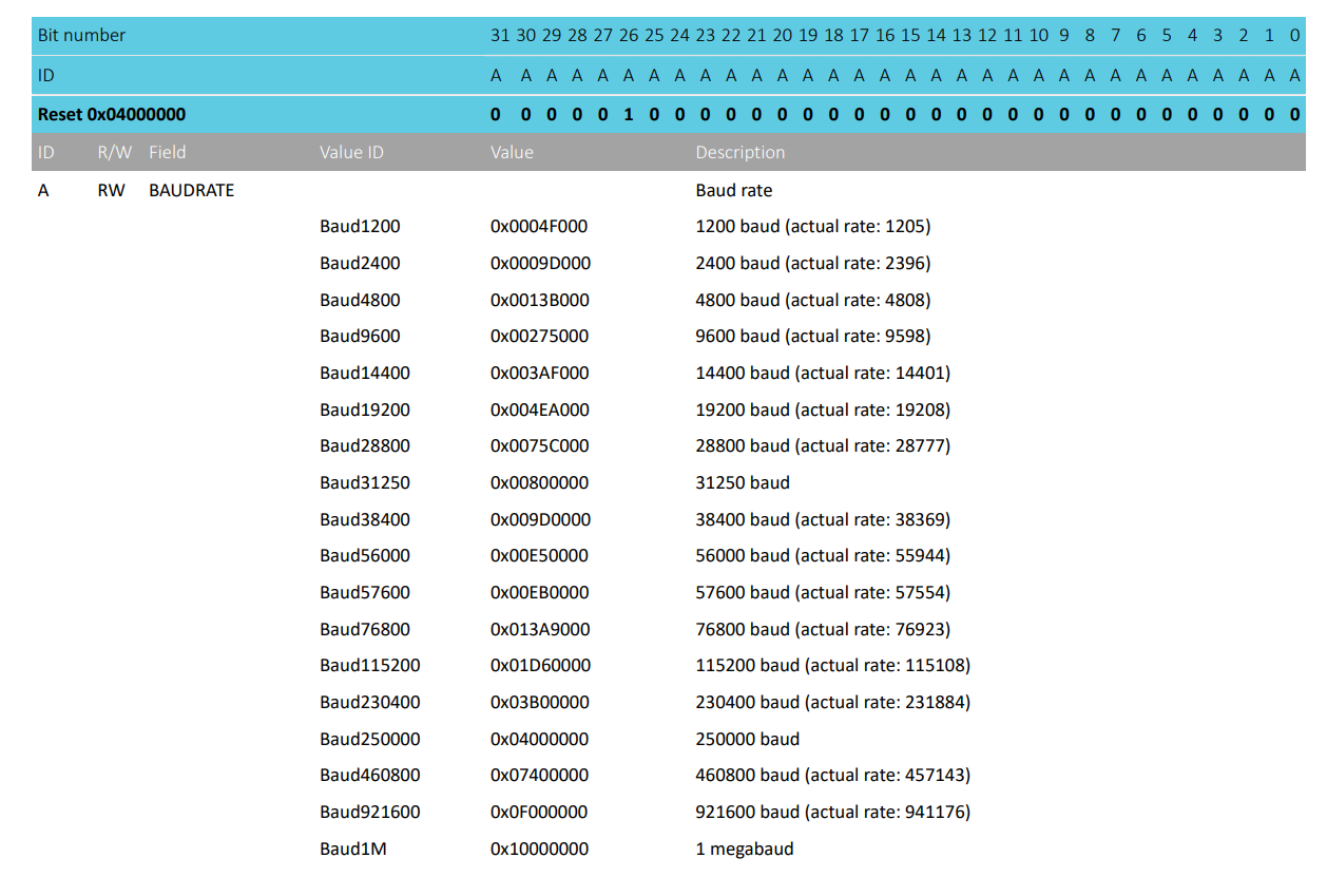
UARTE_BAUDRATE_REG = 0x10000000; // 1 Mbaud
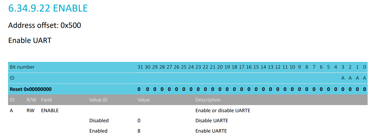
UARTE_ENABLE_REG = 8;             // Enable UARTE
Datasheet Reference
Create a mutex to guard exclusive access to the UARTE0 peripheral:
static SemaphoreHandle_t uarte_mutex = NULL;

// ...

uarte_mutex = xSemaphoreCreateMutex();
This prevents concurrent access from multiple tasks, which could corrupt the peripheral state or produce invalid UARTE transfers.
Recovery
The uarte_recover() function handles recovery if the peripheral runs into trouble during operation. Nothing special here: it stops any ongoing transmission, disables UARTE, clears the relevant events and state, and then re-enables the peripheral.
// signal the peripheral to stop transmission and wait
// until tx is fully stopped ...

UARTE_ENABLE_REG = 0; // Disable UARTE

// clear events, reset state, pin high, etc. ...

UARTE_ENABLE_REG = 8; // Enable UARTE
NOTE: The TX pin is also driven high during recovery to keep the UART line in its idle state while UARTE is disabled — similar to the
uarte_init()function.
EasyDMA transmission
The data that needs to be sent over UARTE needs to be in Data RAM because EasyDMA can only access Data RAM. So, I have a static buffer for that (because static variables live in RAM):
#define UART_TX_BUF_SIZE 256
static uint8_t tx_buf[UART_TX_BUF_SIZE];
NOTE: This is a writable buffer and writable global/static variables are placed in the
.bsssection (if uninitialized). So, it lives in Data RAM at runtime.
Wait, there is more...
Continue reading on my website →
The complete series is maintained on my personal website, where I publish new articles, corrections, diagrams, and project updates first. Read the series there →.


